Denavit-Hartenberg (DH) Parameters
Moses C. Nah
2023-03-19
Introduction
In this post, we discuss about Denavit-Hartenberg (DH) parameters. DH parameters is one of the popular methods for analyzing the Forward Kinematics of a robotic manipulator. There are three main DH parameter conventions [1], including the original notation suggested by Denavit and Hartenberg [2], [3]. Here, we introduce the modified (or) DH parameters [1].
Denavit-Hartenberg (DH) Convention
Consider an \(n\)-DOF open-chain robotic manipulator which consists of \(n\) rigid links. We define two reference frames — frame \(\{S\}\) fixed to the ground and frame \(\{B\}\) attached to the end-effector of the \(n\)-th link. robot. For this section, we simply substitute frame \(\{S\}\) to frame \(\{0\}\).
Given the \(n\) generalized coordinates of the robotic manipulator \(\mathbf{q}=(q_1, q_2, \cdots, q_n)\in\mathbb{R}^{n}\), the goal is to find the orientation and position of the end-effector. In other words, we aim at finding the Forward Kinematics map of the robotic manipulator \({}^{0}\mathbf{H}_{B}(\mathbf{q}) \in SE(3)\) as a function of the generalized coordinates of the robotic manipulator.
One can derive the Forward Kinematics map by defining a sequence of \(n\) reference frames to the \(n\) joints of the robot, and define the relation between the adjacent frames: \[ {}^{0}\mathbf{H}_{B}(\mathbf{q}) = {}^{0}\mathbf{H}_{1}(q_1) {}^{1}\mathbf{H}_{2}(q_2) \cdots {}^{n-1}\mathbf{H}_{n}(q_n) {}^{n}\mathbf{H}_{B} \] In this equation, frame \(\{i\}\) for \(i=0,1,\cdots, n\) is attached to the \(i\)-th link of the robot. For \(i=0\), we consider the fixed ground as the \(0\)-th link (i.e., base frame) of the robot. Moreover, \({}^{n}\mathbf{H}_{B}\in SE(3)\) since frame \(\{n\}\) and frame \(\{B\}\) are both attached to the \(n\)-th link.
Rather than defining these reference frames in an arbitrary fashion, DH convention is a set of rules for placing this sequence of reference frames.
Defining the Reference Frames
Given frame \(\{B\}\) attached at the end-effector of the robot, one has to define \(n+1\) reference frames — frame \(\{0\}\) to frame \(\{n\}\). Each reference frame consists of three mutually orthonormal bases. We denote the bases of frame \(\{i\}\) as \(\hat{X}_i, \hat{Y}_i, \hat{Z}_i\).
DH convention provides a set of rules to define \(\hat{X}_i, \hat{Y}_i, \hat{Z}_i\) for \(i = 0,1,\cdots, n\).
- (Step 1) For \(i= 1, 2, \cdots, n\), attach \(\hat{Z}_i\) along the \(i\)-th joint. If the \(i\)-th joint is a revolute joint, \(\hat{Z}_i\) coincides with the axis of rotation. If the \(i\)-th joint is a prismatic joint, \(\hat{Z}_i\) coincides with the axis of translation.
- (Step 2) Given \(\hat{Z}_1, \hat{Z}_2, \cdots, \hat{Z}_n\) from step 1, consider a pair of adjacent axes \(\hat{Z}_{i}\) and \(\hat{Z}_{i+1}\) for \(i=1,2,\cdots,n-1\). Find a line segment which is mutually orthogonal to the adjacent joint axes \(\hat{Z}_i\) and \(\hat{Z}_{i+1}\). For \(i=1,2,\cdots,n-1\), the origin of the \(i\)-th frame is the point where the perpendicular line segment intersects with \(\hat{Z}_{i}\).
- (Step 3) For \(i=1,2,\cdots,n-1\), the \(\hat{X}_{i}\) axis is along the perpendicular line segment defined in step 2, directed from the \(i\)-th joint to the \(i+1\)-th joint.
- (Step 4) For \(i=1,2,\cdots,n-1\), the \(\hat{Y}_{i}\) axis is immediately defined using the right-hand rule. At this moment frame \(\{1\}\), \(\{2\}\), , \(\{n-1\}\) are fully defined.
- (Step 5) Frame \(\{0\}\) is defined using frame \(\{1\}\). Axes \(\hat{X}_n, \hat{Y}_n\) of frame \(\{n\}\) are defined using frame \(\{n-1\}\).
Details of step 5 are deferred to the later section of this post.
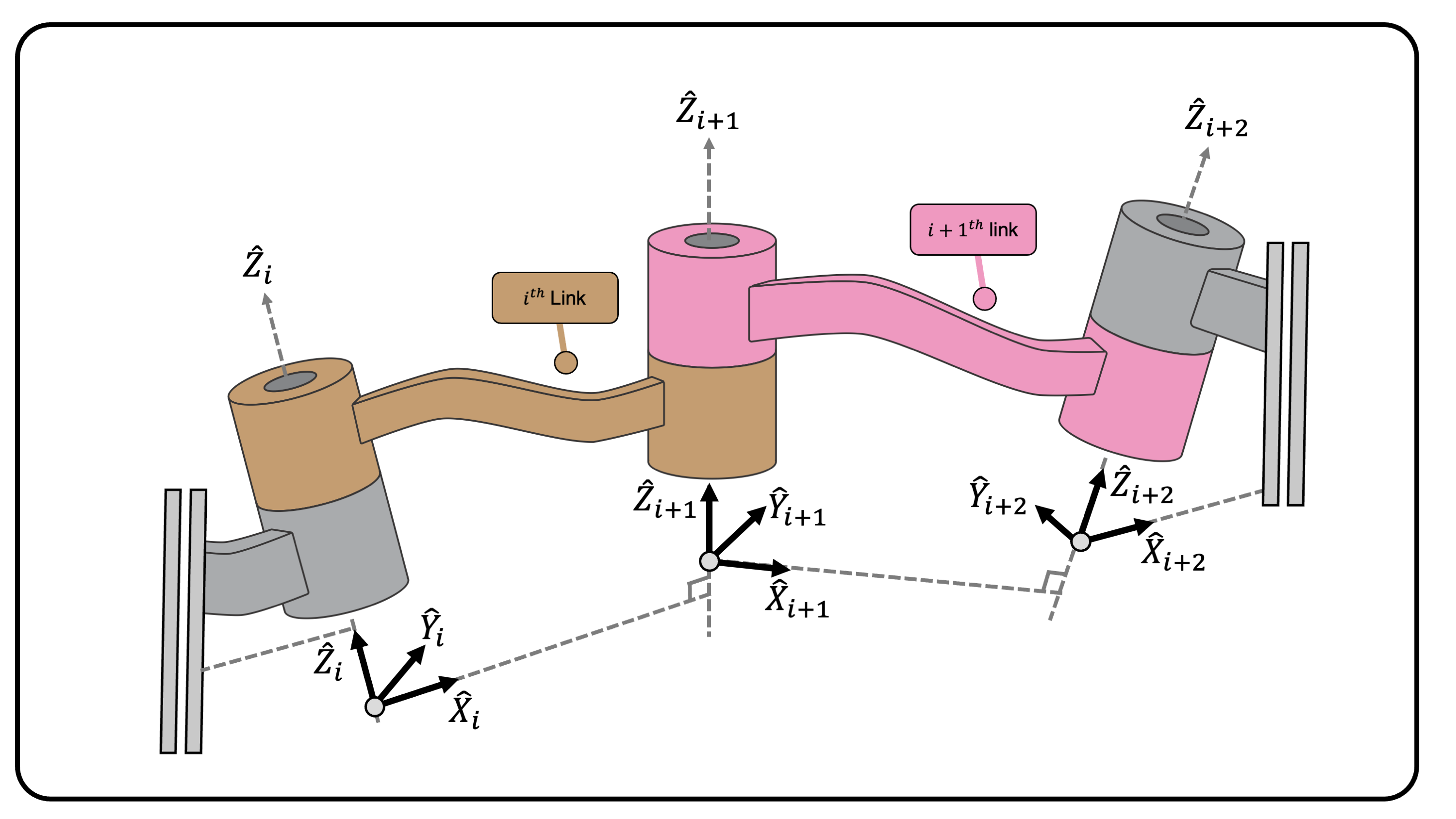
(Figure 1) The reference frames using the DH convention
Managing Exceptions
For step 2, there are two cases where the line segment which intersects the adjacent joints (1) does not exists or (2) is not unique. In detail, for \(i=1,2,\cdots, n-1\):
- When adjacent joint axes \(\hat{Z}_i\) and \(\hat{Z}_{i+1}\) intersect, then there is no
line segment that is mutually orthogonal to both axes. For this case,
\(\hat{X}_i\) is defined to be the
cross product of \(\hat{Z}_i\) and
\(\hat{Z}_{i+1}\), i.e., \(\hat{X}_i:=\hat{Z}_i\times
\hat{Z}_{i+1}\).
- When adjacent joint axes \(\hat{Z}_i\) and \(\hat{Z}_{i+1}\) are parallel, there are infinite many line segments that is mutually orthogonal to both axes. For this case, we simply choose one line segment that is most convenient.
The meaning of convenient is clarified in the next section.
The Four DH Parameters
The DH convention enables us to define (1) the reference frames and (2) the four parameters to define \({}^{i-1}\mathbf{H}_i(q_i),~~ i=1,2,\cdots n\). First, the reference frames are defined as follows.
Limitation of DH Parameters
While the DH parameters serve the minimal representation. This confuses the readers. A superior and better representation is using the Product of Exponentials formula to calculate the forward kinematics.